
Type: Presses, Forming
Manufacturer: HUFFORD
Highlights:
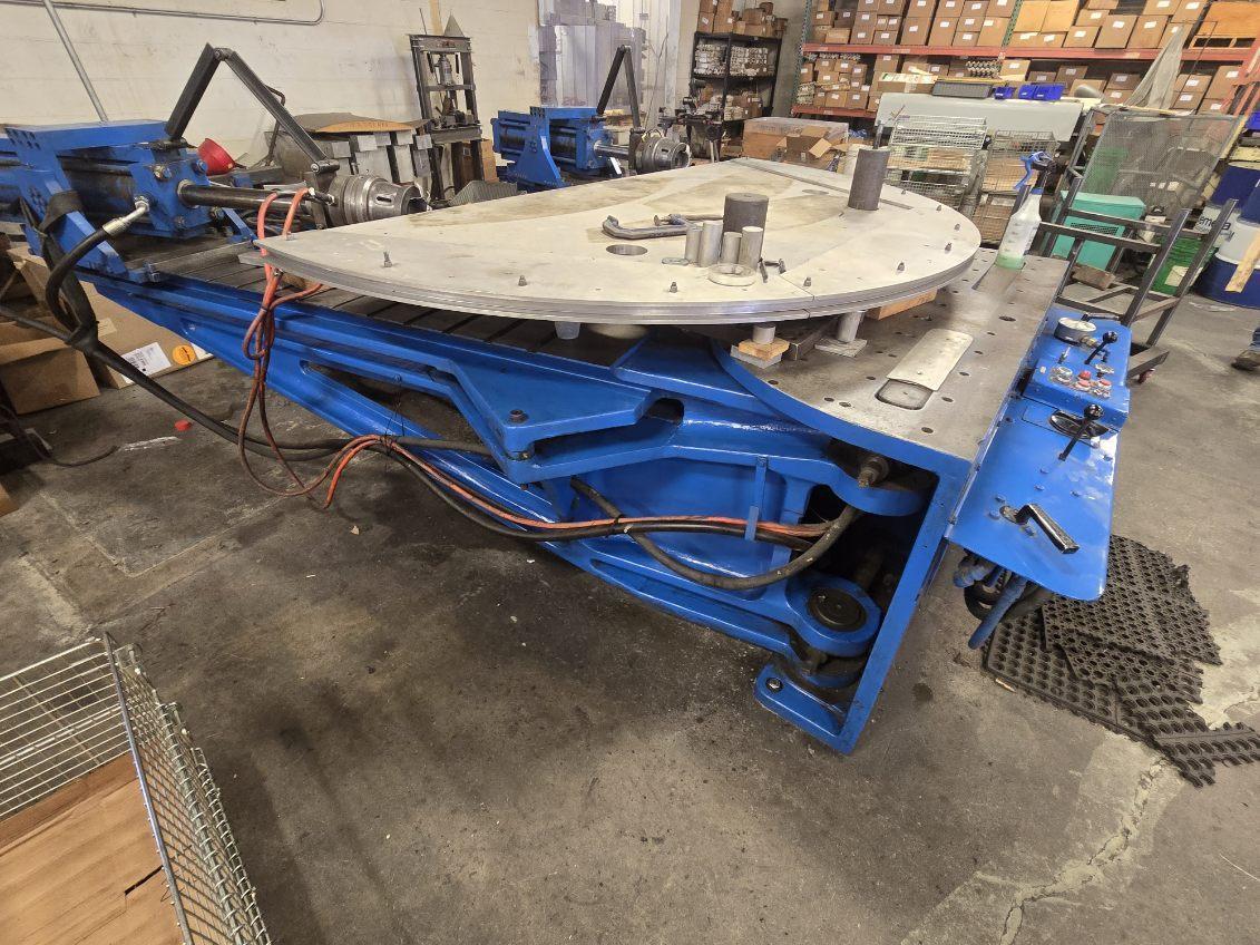
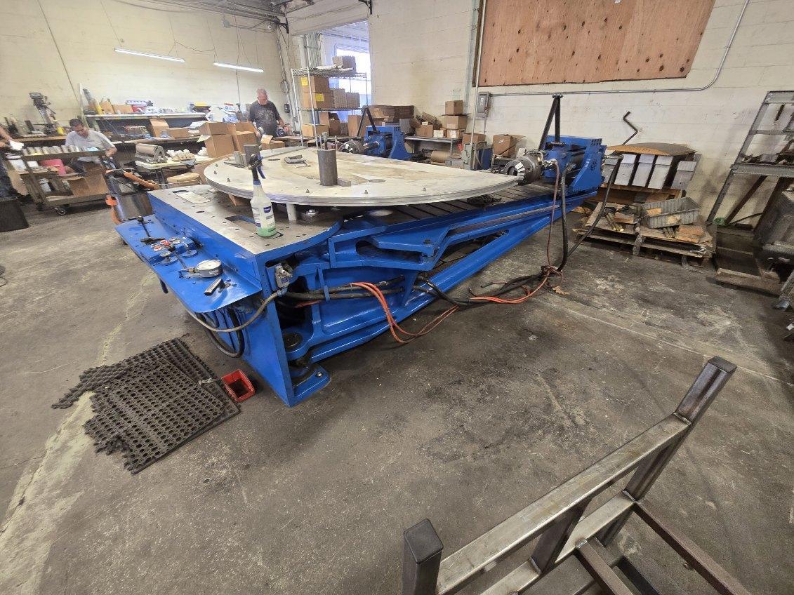
Hufford MODEL A-10 Technical Description
TENSION CYLINDERS ..
Bore ...................................... _............................................ 5.125 inches
Rod...................................................................................... 2 inches
Stroke ................................................................................. I8.5 inches
Maximum pull at 2,000 psi.......................... 35,000 pounds
Tension cylinders are free to swivel about a
vertical axis in the tension cylinder brackets, allowing
the jaw to pull 20° in back of and 20° in front of the
arm center line. ·
The tension cylinder bracket is adjustable along
the arm in 5-inch increments by means of hand-crank
driven gear and rack. This adjustment provides a
range of distances between jaws varying from 6 inches
to 219 inches. (Up to 298 inches with AD-I attachments.)
Anti-rotation links are provided to prevent jaws
from rotating during forming cycle; however, they
may be disconnected when rotation is desired.
Model A-10 machines will accommodate AD-5,.
AD-8 and AD-9 jaws for extrusions and 10 inch sheet
jaws.
ARM ACTUATING CYLINDER
Bore ..................................................................................... 5.125 inches,
Rod................................ ............................. ........ ............. 2 inches
Stroke ................................................................................ 52 inches
Maximum pull at 1,000 psi......................... 17,400 pounds
Maximum thrust at 1,000 psi ...................... 20,600 pounds
The rod end of the arm actuating cylinder is
connected to a cross head which travels on ways along
the center line of the machine. The arms of the
machine are connected to this cross head by links.
Each arm swings simultaneously about its pivot, up to
a maximum arc of 90°. Position of each pivot pin is
adjustable from 12 inches to 25 inches from the center
line Of the machine.
POWER UNIT
Hydraulic oil tank and pumping unit, located at
rear of the press, consists of a 15-horsepower, 1,200
R.P.M. motor driving two Vickers vane-type pumps.
One pump provides power for the arm actuating
cylinder circuit and the other pump powers the tension
cylinders.
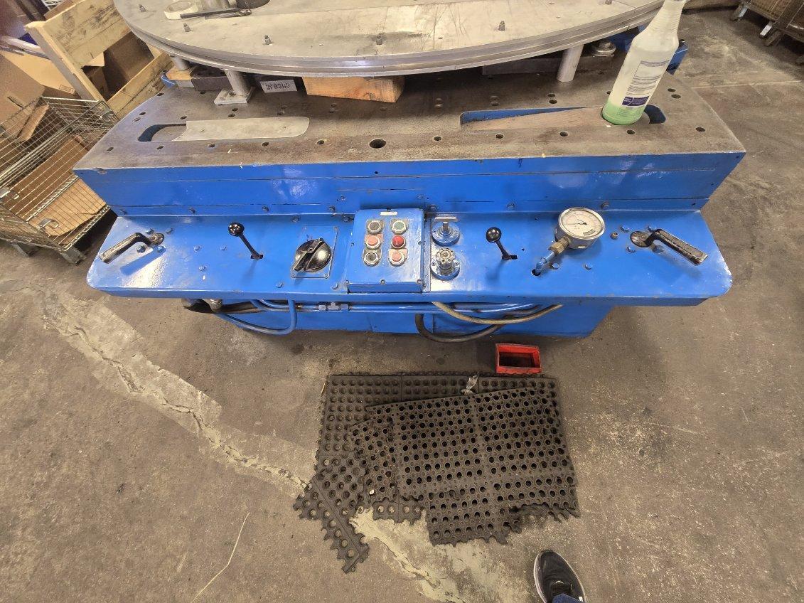
CONTROLS (Located at front of machine)
Two selector valves control directions of tension
cylinders.
A two-stage pressure control valve provides an independent
setting for wrapping pressure; another
for the final stretching pressure, and provides a
'means of unloading the pump when the press is
not forming parts.
One selector valve controls direction of arm movement.
A flow control valve governs rate of speed of arm
movement. Maximum speed is 90° in 12 seconds.
Adjustable automatic stop limits travel o£ arms.
. GENERAL INFORMATION STANDARD WITH AD-1 ATTACHMENTS
Over-all width
of machine ............................ 23'- 6" 31' - 6'
Over-all depth ....................... 12 - 9" 14' -11"
Over-all height ....................... 4' - 7" 4' -7"
Total weight.. .................... : .. l3,000 pounds 16,000 pounds
Table width ............................ 65" 65"
Table depth ....... : ............ .... .30" 30"
Table height. ................. ...... 35~1/2" 35 1/2"
Vertical distance
between center line
of tension cylinders
and top of table..................... 5 3/8 " 5 3/8
Maximum width of
sheet that can be
formed .. -............................... 10" 10"
Minimum die length
for 180° bend at
any tonnage ................ .......... 20" 20"
Maximum die length
for 180° bend at
full tonnage .........................;... 68" 68"
(Proportionately .longer dies may be used at lower tonnages.)
|
Stock #: 117329
SPECIFICATIONS:

Hufford MODEL A-10 Technical Description
TENSION CYLINDERS ..
Bore ...................................... _............................................ 5.125 inches
Rod...................................................................................... 2 inches
Stroke ................................................................................. I8.5 inches
Maximum pull at 2,000 psi.......................... 35,000 pounds
Tension cylinders are free to swivel about a
vertical axis in the tension cylinder brackets, allowing
the jaw to pull 20° in back of and 20° in front of the
arm center line. ·
The tension cylinder bracket is adjustable along
the arm in 5-inch increments by means of hand-crank
driven gear and rack. This adjustment provides a
range of distances between jaws varying from 6 inches
to 219 inches. (Up to 298 inches with AD-I attachments.)
Anti-rotation links are provided to prevent jaws
from rotating during forming cycle; however, they
may be disconnected when rotation is desired.
Model A-10 machines will accommodate AD-5,.
AD-8 and AD-9 jaws for extrusions and 10 inch sheet
jaws.
ARM ACTUATING CYLINDER
Bore ..................................................................................... 5.125 inches,
Rod................................ ............................. ........ ............. 2 inches
Stroke ................................................................................ 52 inches
Maximum pull at 1,000 psi......................... 17,400 pounds
Maximum thrust at 1,000 psi ...................... 20,600 pounds
The rod end of the arm actuating cylinder is
connected to a cross head which travels on ways along
the center line of the machine. The arms of the
machine are connected to this cross head by links.
Each arm swings simultaneously about its pivot, up to
a maximum arc of 90°. Position of each pivot pin is
adjustable from 12 inches to 25 inches from the center
line Of the machine.
POWER UNIT
Hydraulic oil tank and pumping unit, located at
rear of the press, consists of a 15-horsepower, 1,200
R.P.M. motor driving two Vickers vane-type pumps.
One pump provides power for the arm actuating
cylinder circuit and the other pump powers the tension
cylinders.
CONTROLS (Located at front of machine)
Two selector valves control directions of tension
cylinders.
A two-stage pressure control valve provides an independent
setting for wrapping pressure; another
for the final stretching pressure, and provides a
'means of unloading the pump when the press is
not forming parts.
One selector valve controls direction of arm movement.
A flow control valve governs rate of speed of arm
movement. Maximum speed is 90° in 12 seconds.
Adjustable automatic stop limits travel o£ arms.
. GENERAL INFORMATION STANDARD WITH AD-1 ATTACHMENTS
Over-all width
of machine ............................ 23'- 6" 31' - 6'
Over-all depth ....................... 12 - 9" 14' -11"
Over-all height ....................... 4' - 7" 4' -7"
Total weight.. .................... : .. l3,000 pounds 16,000 pounds
Table width ............................ 65" 65"
Table depth ....... : ............ .... .30" 30"
Table height. ................. ...... 35~1/2" 35 1/2"
Vertical distance
between center line
of tension cylinders
and top of table..................... 5 3/8 " 5 3/8
Maximum width of
sheet that can be
formed .. -............................... 10" 10"
Minimum die length
for 180° bend at
any tonnage ................ .......... 20" 20"
Maximum die length
for 180° bend at
full tonnage .........................;... 68" 68"
(Proportionately .longer dies may be used at lower tonnages.)